

Product Details
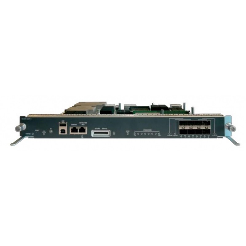
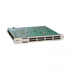
WS-X45-SUP8-E
Original price was: $24,150.00.$6,467.00Current price is: $6,467.00.
| Model: | WS-X45-SUP8-E Catalyst 4500 E-Series Supervisor 8-E |
| Detail: | Cisco 4500 E-Series Supervisor WS-X45-SUP8-E, up to 928 Gbps system bandwidth |
Description
WS-X45-SUP8-E= Specification |
|
|
Chassis compatibility |
The Supervisor Engine 8-E is supported on the Catalyst 4503-E, Catalyst 4506-E, Catalyst 4507R+E, Catalyst 4510R+E, Catalyst 4507R-E1, and Catalyst 4510R-E switch chassis. |
|
Software requirements (minimum) |
Refer to your software release notes for the latest software release requirements |
|
Chassis slot restrictions |
Catalyst 4503-E: Slot 1 only Catalyst 4506-E: Slot 1 only Catalyst 4507R+E: Slot 3 and slot 4 (redundant supervisor engines supported) Catalyst 4510R+E: Slot 5 and slot 6 (redundant supervisor engines supported) Catalyst 4507R-E: Slot 3 and 4 (redundant supervisor engines supported) Catalyst 4510R-E: Slot 5 and 6 (redundant supervisor engines supported) |
|
Bandwidth per slot |
48-Gbps |
|
Feature |
|
|
STATUS LED |
The status LED indicates the current health of the supervisor engine and the current software state. |
|
RESET switch |
The RESET switch is used to reset and restart the switch. Note The reset switch is recessed into the front panel; you need to use a paper clip or other small, pointed object to press the RESET switch. |
|
DC STATUS LED |
The DC status LED indicates the current status of the wireless daughter card. |
|
UID switch and LED |
A combination push button switch and LED indicator. The blue LED can be turned on either by pressing the UID switch on the front panel or through software. The main purpose of the beacon LED is to enable identification from a remote location during configuration or troubleshooting. The ability to turn on/off the LED by pressing a switch allows you to walk to the other side of a fully populated rack and identify the switch. Pressing the blue beacon LED switch toggles the beacon LED on and off. |
|
USB ports |
USB ports are supported with hardware revision 1.1 or higher. |
|
CONSOLE port |
This is a 10/100/1000 port that uses an RJ-45 connector. The console port allows you to access the switch either locally (with a console terminal) or through a modem (remote). The port has an RJ-45 connector. The console port allows you to perform the following functions: Configure the switch from the CLI Monitor network statistics and errors Configure SNMP agent parameters |
|
LINK LED |
The 10/100/1000 MGT port has a link LED associated with it.. |
|
10/100/1000 MGT port |
The Ethernet management port is a Layer 3 host port to which you can connect a PC. You can use the Ethernet management port instead of the switch console port for network management. When managing a switch, connect the PC to the Ethernet management port on a Catalyst 4500 E-series switch. Note When connecting a PC to the Ethernet management port, you must assign an IP address. |
|
SECURE DIGITAL slot |
A standard Secure Data (SD) memory card interface is provided on the front panel |
|
SD LED |
The SD LED indicates the current status of the SD memory card slot. |
|
ACTIVE SUP LED |
The active supervisor engine LED indicates whether the supervisor engine is active or in standby mode in redundant supervisor engine configurations. |
|
UTILIZATION LEDs |
Eight LEDs indicate (as an approximate percentage) the current traffic load over the backplane. |
|
1G/10G UPLINKS (SFP/SFP+) ports |
The Supervisor Engine 8-E has eight 1-G or 10-G ports that use either SFP transceivers or SFP+ transceivers. |
|
Uplink port LEDs |
The Uplink port LEDs display status and activity of the uplink ports. |
|
Supervisor Engine 8-E Front Panel LEDs |
|
|
STATUS |
Indicates the status of the supervisor engine. Green—All diagniostic tests have passed. Orange—System boot or a diagnostic test is in progress. Red—A diagnostic test failed. Off—The supervisor engine is disabled or is not powered up. |
|
DC STATUS |
Indicates the status of the wireless daughter card. Green—Normal operation. Flashing green—The daughter card is booting. Flashing orange—The system is waiting user input. Orange—A diagnostic test failed. Off—No power to the daughter card. |
|
LINK |
Indicates the status of the 10/100/1000BASE-T Ethernet management port. Green—The link is operational. Off—No signal is detected or there is a link configuration failure or the link is disabled by user. |
|
SD |
Indicates the status of the secure digital port. Green—SD card is inserted. Off—SD card has been removed, or the SD card is bad. |
|
ACTIVE SUP |
Indicates whether the supervisor engine is active or standby. Green—Supervisor engine is active (in redundant supervisor engine configurations) Off—Supervisor engine is in standby mode (in redundant supervisor engine configurations) |
|
UTILIZATION |
When the switch is operational, the eight utilization LEDs indicate the current traffic load over the backplane as an approximate percentage value. Each LED lit green indicates approximately 12.5 percent of load. |
|
Uplink port status |
Indicates the status of the uplink port. Green—The link is operational. Orange—The link is disabled by user. Flashing orange—The power-on self-test indicates a faulty port. Off—No signal is detected or there is a link configuration failure. |
|
Uplink port active |
Three LEDs on the front panel show the uplink port activity. 1-2 ACTIVE indicates ports 1 and 2 are active 3-4 ACTIVE indicates ports 3 and 4 are active 5-8 ACTIVE indicates ports 5 through 8 are active In standalone supervisor engine configurations, all eight uplink ports are active; all of the ACTIVE LEDs are lit green. In redundant supervisor engine configurations, only the 1-2 ACTIVE LED and 3-4 ACTIVE LED are lit green. |